Collisions
There are two different collision types that you may use: collision between different objects and internal collision. We should set one thing straight from the start: the primary targets of the collision calculation are the vertices of a Soft Body. So if you have too few vertices too few collision takes place. Secondarily, you can use edges and faces to improve the collision calculation.
Collisions with other objects
For a Soft Body to collide with another object there are a few prerequisites:
- If Collision Group is set, the object must belong to the group. Otherwise, both objects have to share a layer, but the layer does not necessarily have to be visible.
- The collision object has to be a mesh object.
- You have to activate the option Collision in the Collision panel of the Physics tab for the collision object. The collision object may also be a Soft Body.
- If you use modifiers such as Array and Mirror you have to activate EV.M.Stack to ensure that collision calculation is based on the modified object. The sequence of Modifiers is not important.
Examples
A Soft Body cube colliding with a plane.
A Soft Body plane colliding with a cube, so no interaction at all.
Collision with Face activated.
A cube colliding with a plane works pretty well Fig. A Soft Body cube colliding with a plane. , but a plane falls right through a cube that it is supposed to collide with Fig. A Soft Body plane colliding with a cube, so no interaction at all. . Why is that? Because the default method of calculation only checks to see if the four vertices of the plane collides with the cube as the plane is pulled down by gravity. You can activate CFace to enable collision between the face of the plane and the object instead Fig. Collision with Face activated. , but this type of calculation takes much longer.
Let us have a closer look at the collision calculation, so you can get an idea of how we might optimize it.
Calculating Collisions
Visualization of the collision of a Soft Body vertex with a plane.
Six Soft Body vertices with different speed.
Soft Body simulation is by default done on a per vertex basis. If the vertices of the Soft Body do not collide with the collision object there will be no interaction between the two objects.
In Fig. Visualization of the collision of a Soft Body vertex with a plane. you can see a vertex colliding with a plane. If a vertex penetrates the zone between Outer and Inner, it is repulsed by a force in the direction of the face normal. The position that a vertex finally ends up in is dependent on the forces that act upon it. In the example gravity and the repulsion force of the face balance out. The speed at which the vertex is pulled out of the collision zone is influenced by the Choke parameter Fig. Parameters for Soft Body calculation. .
Now lets see what happens if we make vertices heavier and let them travel at a faster speed. In Fig. Six Soft Body vertices with different speed. you can see vertices traveling at different speeds. The two on the far right (5 and 6) are traveling so fast that they pass right through the collision zone (this is because of the default solver precision, which we can fix later). You will notice that the fourth vertex also travels quite fast and because it is heavier it breaches the inner zone. The first three vertices collide correctly.
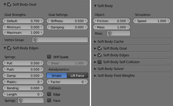
Also Edges and Faces can be used for the collision calculation.
You can set up your collision so that edges and even faces are included in the collision calculation Fig. Also Edges and Faces can be used for the collision calculation. . The collision is then calculated differently. It is checked whether the edge or face intersects with the collision object, the collision zones are not used.
Good collisions
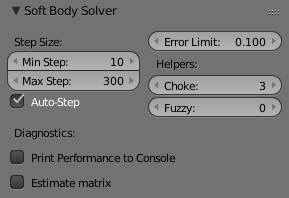
Parameters for Soft Body calculation.
If the collision you have set up is not behaving properly, you can try the following:
Add Loop Cuts to your Soft Body object in strategic areas that you know are most likely to be involved in a collision.
- The Soft Body object must have more subdivisions than the collision object.
- Check the direction of the face normals.
- If the collision object has sharp spikes they might penetrate the Soft Body.
- The resolution of the solver must match the speed at which Soft Body vertices are traveling. Lower the parameter Error Lim and carefully increase Min S.
- Outer and Inner should be large enough, but zones of opposite faces should not overlap, or you have forces in opposite directions.
- If you use strong forces you should use large zones.
- Set Choke to a high enough value (all the way up if necessary) if you have difficulties with repelled vertices.
- Colliding faces are difficult to control and need long calculation times. Try not to use them.
Often it is better to create a simplified mesh to use as your collision object, however, this may be difficult if you are using an animated mesh.
Self Collision
Self Collision is working only if you have activated Use Edges.
When enabled, allows you to control how Blender will prevent the Soft Body from intersecting with itself. Every vertex is surrounded with an elastic virtual ball. Vertices may not penetrate the balls of other vertices. If you want a good result you may have to adjust the size of these balls. Normally it works pretty well with the default options.
Ball Size Calculation Man (“manual”) The Ball Size directly sets the ball size (in BU). Av (“average”) The average length of all edges attached to the vertex is calculated and then multiplied with the Ball Size setting. Works well with evenly distributed vertices. Min / Max The ball size is as large as the smallest/largest spring length of the vertex multiplied with the Ball Size. AvMiMax (“average min/max”) Size = ((Min + Max)/2) × Ball Size. Ball Size
Default 0.49 BU or fraction of the length of attached edges. The edge length is computed based on the algorithm you choose. You know how when someone stands too close to you, and feel uncomfortable? We call that our “personal space”, and this setting is the factor that is multiplied by the spring length. It is a spherical distance (radius) within which, if another vertex of the same mesh enters, the vertex starts to deflect in order to avoid a self-collision.
Set this value to the fractional distance between vertices that you want them to have their own “space”. Too high of a value will include too many vertices all the time and slow down the calculation. Too low of a level will let other vertices get too close and thus possibly intersect because there will not be enough time to slow them down.
Stiffness Default 1.0. How elastic that ball of personal space is. Damping Default 0.5. How the vertex reacts. A low value just slows down the vertex as it gets too close. A high value repulses it.
Collisions with other objects are set in the (other) Collision panel . To collide with another object they have to share at least one common layer.
Collision
Particles , Soft Bodies and Cloth objects may collide with mesh objects. Boids try to avoid Collision objects.
You may limit the effect on particles to a group of objects (in the Field Weights panel ).
Deflection for soft body objects is difficult, they often penetrate the colliding objects.
Hair particles ignore deflecting objects (but you can animate them as soft bodies which take deflection into account).
If you change the deflection settings for an object you have to recalculate the particle, soft body or cloth system by Delete Bake, this is not done automatically.

A collider object can be temporarily disabled via an animatable toggle to the right of the button that permanently activates or deactivates it.
Options
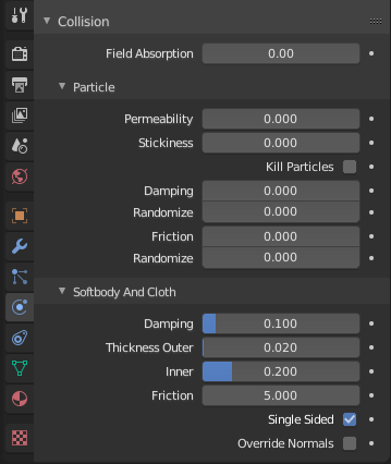
Collision
A deflector can also deflect effectors. You can specify some collision/deflector objects which deflect a specific portion of the effector force using the Field Absorption value. 100% absorption results in no force getting through the collision/deflector object at all. If you have three collision object behind each other with e.g. 10%, 43% and 3%, the absorption ends up at around 50% \(100 × (1 — 0.1) × (1 — 0.43) × (1 — 0.03)\) .
Particle
Fraction of particles passing through the mesh.
How much particles stick to the object.
Deletes Particles upon impact.
Damping during a collision (independent of the velocity of the particles).
Random variation of damping.
Friction during movements along the surface.
Random variation of friction.
Soft Body and Cloth
It is also important to note that this collision panel is used to tell all simulations that this object is to participate in colliding/deflecting other objects on a shared layer (particles, soft bodies, and cloth).
The object’s shape deforms the cloth, so the cloth simulation must be inputted the “true” shape of that mesh object at that frame. This true shape is the basis shape as modified by shape keys or armatures. Therefore, the Collision Modifier must be after any of those. The image to the right shows the Modifiers panel for the Character mesh object (not the cloth object).
Damping during a collision. The amount of bounce that the surfaces will have.
0.0 — No damping, soft bodies will have a maximum bounciness.
1.0 — Maximum damping, soft bodies will not bounce at all.
A padding distance is added to the inside and outside of each face, to help to prevent intersections. The soft body will come to rest at this distance away from the face of the colliding object. Outside and inside is defined by the face normal, depicted as blue arrow in Fig. A soft body vertex colliding with a plane. .
Size of the outer collision zone.
Size of the inner collision zone (padding distance).
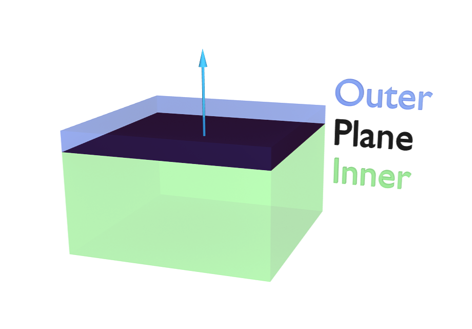
A soft body vertex colliding with a plane.
A coefficient for how slippery the cloth is when it collides with itself. For example, silk has a lower coefficient of friction than cotton.
When enabled, the collider is considered to represent the boundary of a solid object rather than a thin surface, and ejects intersecting cloth in the direction of its normal.
When enabled, cloth collision impulses act in the direction of the collider normals.
Soft body collisions are difficult to get perfect. If one of the objects move too fast, the soft body will penetrate the mesh. See also the section about Soft Bodies .
Examples
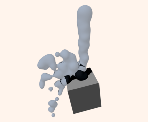
Here is a Meta object, using Instancing Vertices to a particle system emitting downwards, and deflected by a mesh cube.
Hints
Make sure that the normals of the mesh surface are facing towards the particles/points for correct deflection. Negative scales on the object can have a similar effect. Make sure to recalculate the normals after applying the scale.
Hair particles react directly to force fields, so if you use a force field with a short range you do not need necessarily collision.
Hair particles avoid their emitting mesh if you edit them in Particle Edit Mode. So you can at least model the hair with collision.
© Copyright : This page is licensed under a CC-BY-SA 4.0 Int. License. Last updated on 02/15/2023.
Столкновения
Частицы, Мягкие тела и Объекты ткани могут сталкиваться с объектами полисетки. При использовании частиц с типом физики Рой старайтесь избегать Столкновения с объектами.
Объекты должны иметь по крайней мере один общий слой, чтобы получить эффект.
Вы можете ограничить воздействие на частицы, используя группы объектов (в панели Весовые коэффициенты поля).
Отражения (дефлекторы) для объектов мягких тел достаточно сложны, они часто проникают через сталкивающиеся объекты.
Частицы волос игнорируют отражатели объектов (но вы можете анимировать их как мягкие тела, которые принимают во внимание этот отражатель).
Если изменить параметр отражение объекта, то необходимо пересчитать частицы, мягкие тела или систему ткани (Очистить кэш), это не будет сделано автоматически. Вы можете очистить кэш выделенных объектов Ctrl-B –> Очистить кэш выделенного.
Опции

Изображение 1: Панель столкновение вкладки Физика.
Доля частиц, проходящих через полисетку. Могут быть анимированы.
Сколько частиц прилипнет к объекту.
Удаляет частицы при столкновении.
Демпфирование во время столкновения (не зависит от скорости частицы).
Случайная вариация затухания.
Трение во время движения вдоль поверхности.
Случайная вариация трения.
Изображения 1b: Вершины мягкого тела сталкиваются с плоскостью.
Мягкое тело и взаимодействие с тканью
Размер внешней зоны столкновения.
Размер внутренней зоны столкновения (расстояние “обивки”).
Наружная и внутренняя стороны определяются нормалью грани (изображается в виде синей стрелки на Изображения 1b).
Демпфирование во время столкновения.
Трудно получить идеальное столкновение мягкого тела. Если один из объектов двигаться слишком быстро, мягкое тело будет проникать через полисетку. См. так же раздел Мягкие тела.
Modeling props with Blender
 Note: Basic working knowledge of Blender is assumed. At the very least, be comfortable with creating simple models, applying UV texture mapping, and installing plugins. A working knowledge of how to compile models is a significant help.
Contents
Creating a basic non-solid prop
1. Create your model and texture it via UV mapping. The result should be a .blend file and all the TGA files you used as textures. The example used here is the PC Gamer UK mag secreted all around de_dust_pcg (blender file for the model pcgmag.blend and texture file pcgmag.tga )
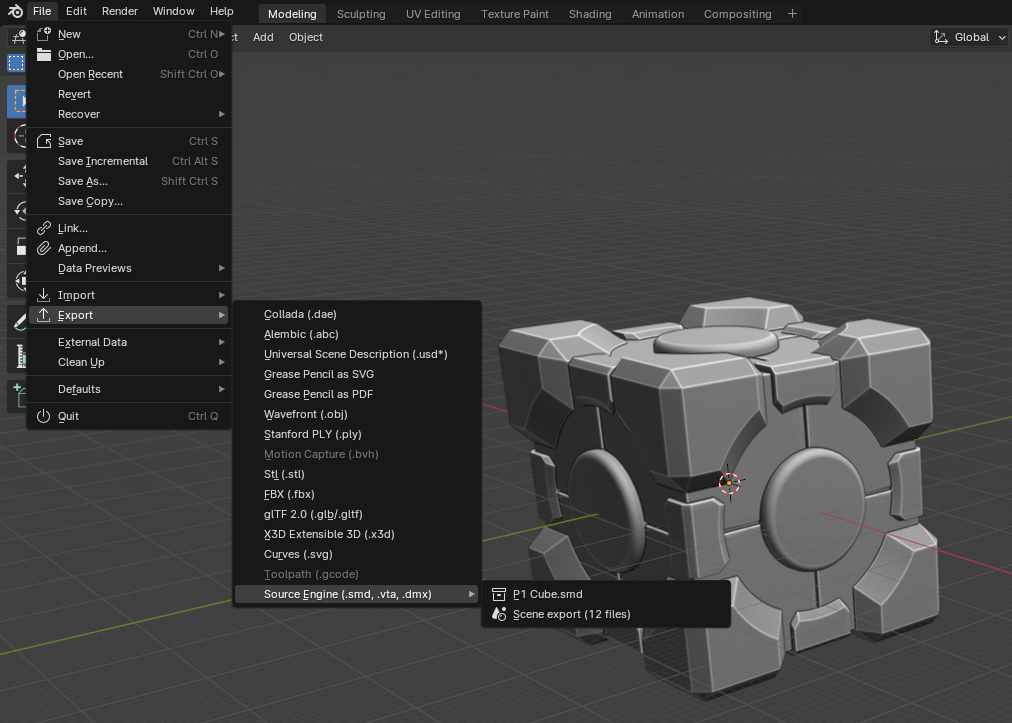
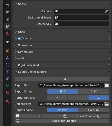
2. Having installed the Blender Source Tools, go to the right panel  +
+  Scene Properties and scroll down until you find the Source Engine Export tab, type in your export path and set the file type to SMD. You can now export your model, in this case pcgmag.smd .
3. For a Counter-Strike Source model, copy the SMD file into SteamApps/username/sourcesdk_content/cstrike/modelsrc and the TGA file(s) into SteamApps/username/sourcesdk_content/cstrike/materialsrc/models
4. The SMD you have already is just the reference model. We will also need an additional SMD to declare the ‘idle’ animation. So, in a text-editor, create a file called pcgmag_idle.smd (or some other name ending in SMD) and enter this as its contents:
5. The compile tools need a QC file containing model information. Here is pcmag.qc (See Compiling a model for more info):
Note the scale factor, which was tweaked to get the magazine to appear at the right size in-game. Note also the $surfaceprop line, which sets the prop’s material surface properties such as its surface friction and associated noises. Unlike a regular brush, any $surfaceprop set in the prop’s material (.VMT) files is ignored; instead, it is set here in the .QC file.
6. The texture must also be compiled into a VTF file just like any normal texture. However, it must include the $model declaration. A good tool for compiling textures for the source engine is VTFEdit. It imports most image types and has a GUI for creating VMT files. This was the VMT file used for pcgmag.tga :
Whatever texture filename used to UV map the model in Blender will be used as the name of the material file for the model. For instance, if it was UV-mapped using pcgmag.tga , the model will use the material pcgmag.vmt . When using textures with long filenames in blender, blender cuts the end of the name off at a certain point. When the model exports, it will look for the abbreviated name that blender used, instead of the actual name of the file. To check what name blender used, have a look in the texture selection box in blender’s image editor (or UV mapping) screen. Before compiling the textures, make sure that the filenames are the same as the name in the texture selection box. You can also change the filenames after compiling and it will work, as long as you also change the filenames in the .vmt file. You can use multiple texture files on the same model.
7. Finally, change to the SourceSDK bin folder containing studiomdl.exe , and compile the model using a command like this:
A good alternative tool for compiling models is GUIStudioMDL. You load in your .qc and hit compile, it also has a range of other options that can be utilized as you get more advanced.
8. If everything went right, you’ll get some nice output from studiomdl (look carefully for any errors), and you can now find the model in Hammer’s model browser for use in-game.
Adding multiple skins
Making the prop have two or more skins is quite easy. For a magazine prop, there could be a variety of different cover textures. First, make a new .VTF texture file, following the same UV mapping layout that was used for the original texture. Also make a copy the first .VMT file (e.g. as pcmag_cover2.vmt ) making sure you update the $baseTexture setting to the new texture.
Now add the following command to your prop’s .QC file, directly following the $body line:
Here «pcgmag» was the original skin texture, and «pcgmag_cover2» is the material file for the second skin. Keep adding extra lines to add more skin textures.
With the model recompiled, and all the texture files in the right place, you can now change the prop’s skin with the Skin entity option in Hammer.
Adding collisions
So far we have a basic model which can be used as a prop_static, but it has no mass. At the moment, players, objects, and bullets will pass right through it. To prevent this, we need to create a collision model.
Creating a collision model is easy for a simple prop like this. We can use the same mesh as the reference model, but in Blender, select the whole mesh and hit «Set Smooth» (under the «Link and Materials» panel of the edit mode). We do this because the model compiler expects the collision model mesh for each convex part to have a single texture and be in one smoothing group. Now export the mesh as «pcmag_phys.smd». This is our collision model.
If the reference mesh isn’t a simple convex shape, but is pretty close, the model compiler will build a «convex hull» around the specified collision model, filling in any concave bits. You could also build a separate collision model by making a cuboid roughly the same size and shape as the prop. (Note that the SMD export script requires a mesh to be UV-mapped, so you will need to apply a UV mapping to the collision model to export it, even though it will never be displayed.) More complex props may be very non-convex, a situation we will handle below.
Adjust the .QC file to add the collision model to the prop. Change pcmag.qc to this:
We’ve just added the $collisionmodel line which refers to the collision mesh. Recompile the model, and when added as a prop_static in Hammer it will be solid. The player and other objects won’t be able to pass through it, and if shot it will stop bullets and be marked by bullet holes.
Adding physics
Now we have a collision model, but the prop is still static: it can’t move, or be affected by explosions or gravity. To do that, we need to add some physics data to the prop.
Edit pcmag.qc again so it looks like this:
We’ve added two sections: after the $collisionmodel line, we’ve added a section in braces, and a new $keyvalues section which specifies some prop data. Note that we still have a $staticprop command, even though we’re no longer making a prop_static. Despite the name, this command isn’t only used to compile prop_statics, but for any prop which doesn’t have animations or need a bone structure (i.e. anything other than prop_dynamics or prop_ragdolls).
The section after $collisionmodel specifies the prop’s mass, in kilograms, with the $mass command between the braces. Set it to 0.5 kg here, which is a typical mass for an advert-laden PC magazine. The $keyvalues section specifies extra information for the model that the game engine can use — here, we set the prop_data for the model. Use the base prop type of «Cardboard.Small,» being the closest thing available to a paper magazine. The prop data is required for any physically simulated prop, and sets things like the health and scale of damage of the prop from different effects. For a full list, see the scripts/propdata.txt file in source engine.gcf or counter-strike source shared.gcf .
Now recompile the .QC file using studiomdl.exe . We can now place the model as a prop_physics in Hammer. It will fall under gravity, collide with objects and the player, and will move around if shot at or caught in an explosion.
Complex collision models
So far, we can create a collision model for a simple convex object, such as a magazine or book. But to make it a non-convex object, such as a table, we have to be more careful if we want the prop to collide with things as we would expect.
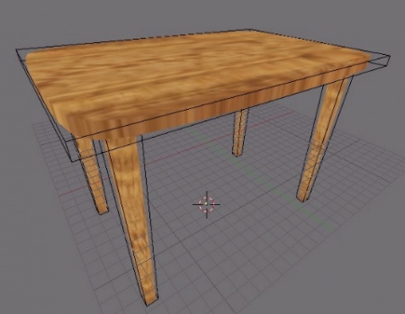
Here’s a wooden table made in Blender. Using subsurfaces It has a top with rounded edges, and tapered, cylindrical legs. It is possible to make the collision model from the same mesh as the table itself, but that would be quite wasteful — collision meshes should be as simple as possible, so the physics engine has to do less work.
The black wireframe shows the collision meshes overlayed on the reference model, by making five separate objects in Blender. The table top is just a simple flat cuboid, and each leg is a tapered cuboid (or a truncated pyramid) following the form of the visible leg. In practice, it would probably be better to clip off the corners of the table top to match the reference model a bit more closely, but this is good enough for an example. Place the collision mesh objects in a separate layer in Blender from the visible model, so that they are easier to edit independently.
It’s important that the object origins of the reference meshes and the collision meshes are in the same place. The easiest way to do this is select all the meshes, place the 3D cursor at the middle of the table, and press the «Centre cursor» button in the Mesh panel. This moves all the selected object’s origins to the cursor; otherwise, the collision model and the visible model may not be aligned in-game, producing some weird effects.
We can export the SMD of the model (table.smd) by selecting the objects and using the export script as before. Make sure you only export to this file the meshes you want visible in-game.
To export the collision model we need to be a little careful. First we have to make sure that each convex part of the collision model is a separate object in Blender. In object mode, when you select the object (right-click), only that part should highlight. If two parts highlight from a single click, then they are in fact both in the same object. You can separate them by going into edit mode, selecting all vertices in one part of the object, and pressing the P key.
The model complier expects each part of a complex collision mesh to be in a separate smoothing group. Blender doesn’t really have the concept of smoothing groups, but we can emulate it by selecting each object in the collision model one at a time, and hitting «Set Smooth». Don’t select all the objects at once and hit «Set Smooth» — this will not produce the same result. Once we’ve done this, select all the collision objects and export them as table_phys.smd. Remember that the exporter script requires all meshes to be UV mapped, so apply a simple UV mapping to the collision meshes (it doesn’t matter what texture you use or what it looks like, since it is never visible), before exporting.
As before, we need a table_idle.smd file to define the idle animation, which can be identical to the pcgmag_idle.smd file we used above.
Now we need a .QC file for the table prop:
Note the differences from before. We’ve upped the scale a little, and set the $surfaceprop to «Wood_Furniture» and the prop data to «Wooden.Large» to reflect the type of prop we’re making. In the $collisionmodel section, instead of the $mass command, we’ve used $automass. This makes the model compiler compute a mass for the object based on its size and material type. We could instead have explicitly specified the object’s mass with the $mass command as before.
We’ve also added the $concave command to that section. This makes the compiler build a non-convex collision mesh for each part of the table_phys.smd file, rather than lump them all together in one convex shape. We can tell if this has worked when compiling the .QC file. The first lines of output from studiomdl.exe should look similar to this:
Note the «model has 5 convex sub-parts» line, which means the collision model worked properly. If instead it read «Model has 1 convex sub-parts», we either didn’t specify the $concave command, or failed to make the collision model meshes correctly.
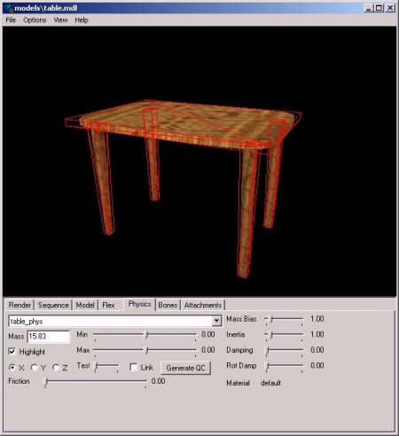
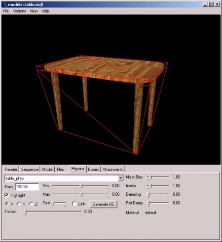
We can check the collision model by using the model viewer ( hlmv.exe ). On the «physics» tab, click the Highlight button and the collision mesh shows as a red wireframe. If we’ve got it right, it should look like the picture on the left: the wireframe follows each part individually. If we’ve got it wrong, it might look the picture on the right: the wireframe is a single shape wrapping the whole object. In game, the table model on the right would behave oddly — we couldn’t shoot between the legs, and if knocked upside-down, object placed on it would hover on the invisible box covering the underside. The model on the left would behave as normal. If you have the problem with the table on the right, where your physics mesh is a single hull, try scaling up your physics model in blender. The compiler needs the faces to be larger than 1 inch on any axis, so if there is a face shorter or skinnier than 1 inch, the compiler will run a warning and generate it’s own physical mesh. Remember to scale up your normal model as well or the physics model and the rendered model won’t match!
Adding custom gib models
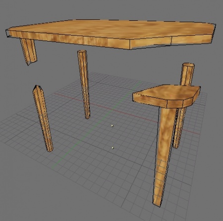
If you’ve made the table model, you’ll find that if damaged enough it will break apart into a few pieces of wood. These are the model’s gibs, and are set in the propdata.txt file for «Wooden.Large» prop types. However, the default wooden gibs don’t really fit our table very well, so we can make some custom models to replace them.
First we have to break up the table model into pieces. First, make a duplicate (SHIFT-D) of the original table and hide it in another layer. Now chop up the table using Blender’s knife tool (SHIFT-K). You can cut one leg of the table halfway up, and broken the tabletop across one corner so that comes away with the second leg. The broken edges have been roughened up to look sufficiently damaged. The other two legs will simply drop-off whole. Remember to add faces (and UV mapping) to the areas of the model that are newly visible — for instance, the tops of the legs, which didn’t need visible faces before, but do now.
Edit the collision models (black wireframes) to match the broken pieces. For some of the legs, make the collision meshes more rounded — this will allow the legs to roll around nicely, which they didn’t need to do when they were attached to the table. Note that two of the gib model (the tabletop with the stump of leg, and the leg with the broken-off corner) have concave collision models, and therefore must be made using the methods detailed in the section above.
You should, as before, ensure that each object’s origin points (including those of the collision meshes) are in the same place (using the «Centre cursor» command), and this should also match the origin point set in the original table. Place the pieces of the gib models so they overlay the positions of the original unbroken model. This will make the gibs spawn in the correct place when the table is broken. (Note that in the picture, the models are slightly apart for clarity.)
Now we need to export and compile the model for each gib, along with their collision meshes. Here’s the .QC file for the tabletop part:
Notice the model name is table_gib_top.mdl . A near-identical .QC file is used for the other four pieces, table_gib_leg1.mdl to table_gib_leg4.mdl . The only real new feature is the $autocenter command, which automatically centers the gib model so that lighting and collisions will work correctly.
With all five gib models compiled, we only need to add a new command to our original table.qc :
This spawns the five gib models when the original breaks. Each gib can get a health value, and also a «fadetime» which is how long (in seconds) before the gib model fades out of view. Setting it to 0 means the model never fades. Now compile table.qc , and the model is complete.
One slightly odd effect is that gib models will not collide with each other (but they will collide with other objects). Making more, smaller gib models would make this less obvious. Also, each gib model can further be broken into the standard wooden gibs if damaged. This is set by each model’s prop_data section.
Download a zip file of the completed table model (including textures and source .blend file) here.