NAT Configuration on Packet Tracer
Network Address Translation NAT Configuration on Packet Tracer
NAT ( Network Address Translation ) is used for security by reusing IP-addresses. The router on which Network Address Translation is configure translates traffic which is accessing internet or coming back to local network. A NAT is the virtualization IP-addresses. This is Simple lab for configuring NAT ( Network Address Translation ) on packet tracer. Our network diagram consist of two parts, one is the LAN which is define as inside network and other is the internet or public network which will be define as outside for network address translation (NAT). For configuring this lab pleas follow these steps:

Task 1: Configure IP addresses and setting a static default route.
Access the CLI and specify the following IP address configuration on both routers
R1 Config:
Router1(config)# int fa1/0
Router1(config-if)# ip address 177.77.77.10 255.255.255.0
Router1(config-if)# no shu
Router1(config)# ip route 192.168.44.0 255.255.255.0 177.77.77.1
R0 config:
Router0(config)# int fa1/0
Router0(config-if)# ip address 177.77.77.1 255.255.255.0
Router0(config-if)# no shut
Router0(config)# int fa0/0
Router0(config-if)# ip address 192.168.44.1 255.255.255.0
Router0(config-if)# no shut
Router0(config)# ip route 200.10.123.0 255.255.255.0 177.77.77.10
Task 2: Configure NAT on Router0
Step 1: Access the CLI on the Router0
Step 2: Configure a standard access list using an access list id of 1 and permit any device on subnet 192.168.44.0 /24
Router0(config)# access-list 1 permit 192.168.44.0 0.0.0.255
Here access list is used to identify which source IPs are going to be translated using NAT, and this example allows any device from the 192.168.44.0 network.
Step 3: Create a dynamic NAT IP-address pool, this will hold a list of inside global addresses.
| Name of Pool: | NAT-POOL |
| Starting IP address | 192.168.44.1 |
| Ending IP address | 192.168.44.14 |
| Network mask | 255.255.255.240 |
Complete this configuration with following commands:
Router0(config)# ip nat pool NAT-POOL 177.77.77.1 177.77.77.7 netmask 255.255.255.240
Router0(config)# ip nat inside source list 1 pool NAT-POOL
For network address translations, we are requires to identify at least two interfaces to be our inside and outside.
Interface fa0/0 will be our inside interface
Interface fa1/0 our outside interface
You can use the following commands for configuring inside and outside interfaces.
R0(config)# int fa0/0
R0(config-if)# ip nat inside
R0(config-if)# int fa1/0
R0(config-if)# ip nat outside
Step6: Testing NAT translation: When we ping from PC1 to PC0 to R1 our original IP address will be translated from a 192.168.44.x to 177.77.77.x.

You can verifiy it after the successful ping from PC1 to PC0 and then use the command “show IP nat translation”.
How to Configure Static NAT in Cisco Packet Tracer
 Last Updated: August 6, 2020 , Tolga Bagci
In this article, we will examine how to add Static NAT on the Router in the Packet Tracer network simulator.
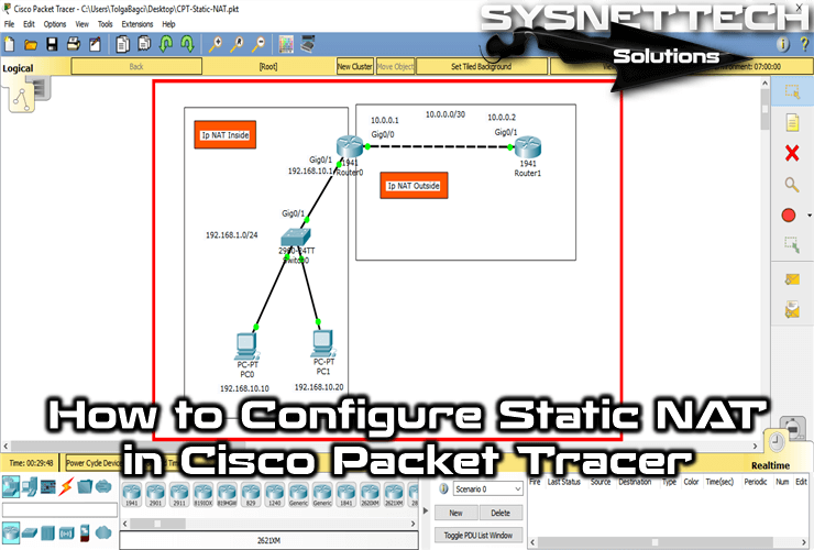
How to Configure Static NAT on Cisco Router
With static NAT, when a computer on the local network sends a packet to the port of an external or optional interface, it maps the destination IP address to a port behind the firewall.
This means that each computer on the private network must have a public IP address assigned to access the Internet. The main disadvantage of this is that you need to add a manual route for each computer you want to access the Internet.
You cannot configure static NAT for connections to a trusted or custom interface. For example; VPN connections.
For Static NAT configuration, you must specify the Inside and Outside fields according to your network design. For the local network, you need to set the Router’s internal interface with the IP NAT Inside command and the external interface with the IP NAT Outside command.
You can follow the steps below to configure a static NAT record on the Router.
Step 1
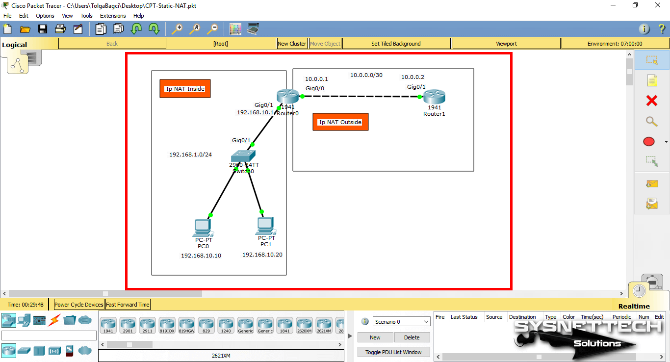
First, open the Packet Tracer and create a network topology as shown in the image below, then specify the Inside and Outside fields and add comments to the workspace.
In the topology below, the interface to the Internet is GigabitEthernet0/0 and is selected as Outside.
Step 2
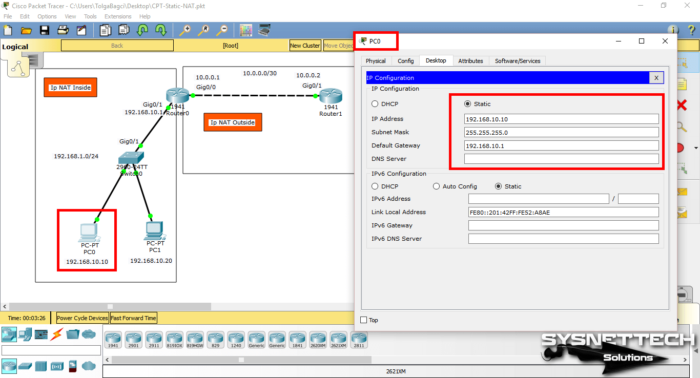
After specifying and configuring the IP blocks for the topology, add two computers to the workspace and configure the TCP/IP settings.
Step 3
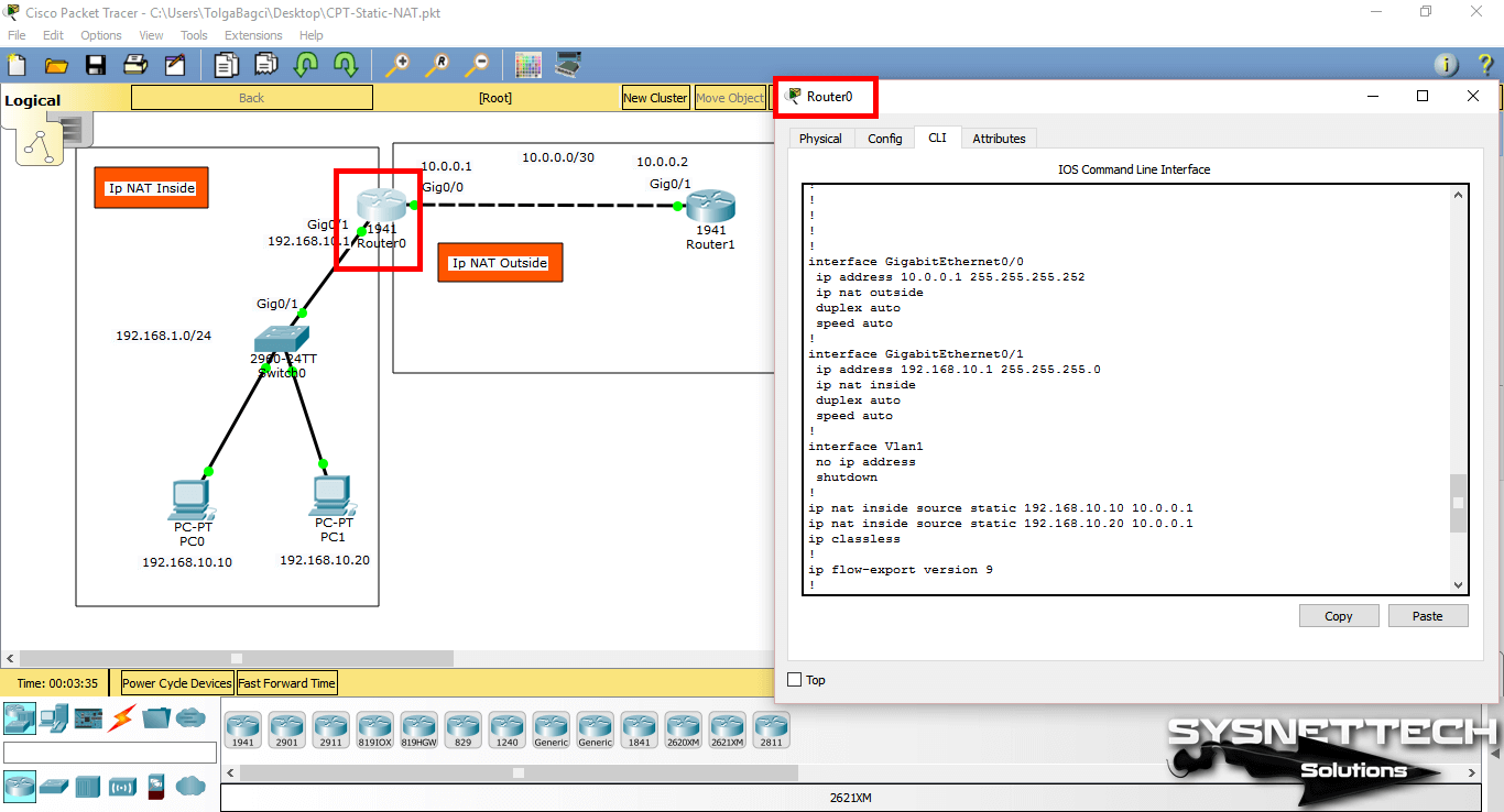
Now, select the Inside and Outside interfaces at the CLI command prompt of Router0 and perform the following commands to add static records for computers with IP addresses 192.168.10.1 and 192.168.20.1.
You can use the command (write / wr) in the privileged mode to save your settings.
Step 4
Now, ping Router1 from computers on the LAN and then check out the NAT records created on the Router using the show ip nat translations command in the CLI.
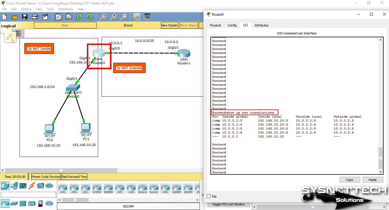
Show Commands
Video
You can watch the video below to add Static NAT to Router and also subscribe to our YouTube channel to support us!
Final Word
In this article, we have examined how to create a static NAT record on a Router using the simulator software. Thanks for following us!
Related Articles
Hello, I’m Tolga! I am a computer specialist who has been specializing in computer technologies for about 20 years. I provide solutions to problems encountered in many areas such as hardware, system, network, virtualization, server systems, and operating systems, and create relevant content on my website by explaining how to solve these problems. My goal is to be a reliable source of expert, quality, and trustworthy solutions for your computer problems. By following innovations and using the latest technologies, I aim to be successful in my job and provide you with the best service. Don’t hesitate to contact me for any questions or curiosity about technology. Have a nice day, stay up to date 🙂
Dynamic NAT Configuration with Packet Tracer
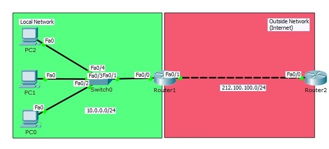
Before this article, we have talked about Static NAT configuration. Here, we will talk about another types of NAT, Dynamic NAT configuration on Packet Tracer. As in Static NAT, in the Dynamic NAT configuration, the interfaces must be identified as inside and outside again. Then we will define a Dynamic Address Pool on the NAT router. The ip address will be choosen in this pool to assign as source ip address.
We will use Dynamic NAT topology below for our Dynamic NAT Configuration example. And we will use Cisco Packet Tracer as a network simulation program.
You can DOWNLOAD the Cisco Packet Tracer example with .pkt format at the End of This Lesson.
You can also DOWNLOAD all the Packet Tracer examples with .pkt format in Packet Tracer Labs section.
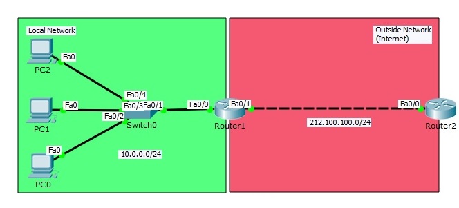
Dynamic NAT (Network Address Translation) Configuration Topology In our Dynamic NAT configuration topology on Packet Tracer, we will have two networks again, one local and one outside network. In local network, we have three PCs and we will provide internet access to these PCs. Our Dynamic NAT configuration topology on Packet Tracer will be a small simulation of real world office Internet access.
Interface IP Configurations
Firstly, before Dynamic NAT configuration, we will prepare our network with our IP configurations on PCS and routers. We will provide full connectivity end to end before starting our NAT Config.
Our PCs on Packet Tracer will be configured with below IP addresses.
PC0 : 10.0.0.2 255.255.255.0 GW:10.0.0.1
PC1 : 10.0.0.3 255.255.255.0 GW:10.0.0.1
PC2 : 10.0.0.4 255.255.255.0 GW:10.0.0.1
Static NAT configuration in Packet Tracer
This tutorial gives a simple step by step explanation of configuring static NAT in Packet Tracer.With static NAT a router or a firewall maps one private IP address to one public IP address.
Now let’s configure this in Packet Tracer.
First build the network topology.

Then configure basic IP addressing on the router, PC and server.
Router
PC: IP add 192.168.1.10 Subnet mask 255.255.255.0 Default gateway 192.168.1.1
Server: IP add 200.0.0.10 Subnet mask 255.255.255.0 Default gateway 200.0.0.1
Now,to configure static NAT on the router,these are the steps:
1.Configure private/public IP address mapping using ip nat inside source static PRIVATE_ID PUBLIC_ID command.
2.Configure the router’s inside interface using ip nat inside command.
3.Configure the router’s outside interface using ip nat outside command.
Here are the configuration commands:
We’re done with configurations.
Now ping the server from the PC to test connectivity and start off address translations.
The PC uses its private IP address when sending a request to the router. R1,which serves as a default gateway,receives the request,changes the private IP address of the PC to the public one,then forwards the request to the internet server.The server responds to the router with a packet destined to the PC.The router looks up in its NAT table and changes the destination IP address to the private IP address of the PC.
To verify NAT,we’ll use the show ip nat translations command:

From the picture above, you can observe that the private IP address(inside local) of the PC has been translated to a pubic IP(inside global). Outside local represents the server(an outside host).